 Back Home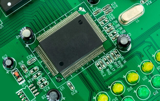
The automotive industry has undergone a remarkable transformation over the past decade. Today’s vehicles are no longer purely mechanical machines—they are sophisticated electronic systems equipped with advanced safety technologies, intelligent connectivity, powerful infotainment systems, and increasingly complex electric drivetrains. At the center of these innovations are Printed Circuit Boards (PCBs), which serve as the foundation for virtually every electronic function inside a modern vehicle.
From traditional gasoline-powered automobiles to hybrid and fully electric vehicles (EVs), automotive PCB assembly plays a critical role in ensuring reliable performance, safety, and efficiency. At YIC Assm, we specialize in providing high-quality PCB assembly solutions designed to meet the demanding requirements of the automotive industry.
The Growing Importance of Automotive PCB Assembly
Every modern vehicle contains dozens—and often hundreds—of electronic control units (ECUs) that communicate continuously to monitor performance, improve safety, and optimize fuel efficiency. Each ECU depends on precision-manufactured printed circuit boards to process information and control essential vehicle functions.
Unlike consumer electronics, automotive PCBs must perform reliably under extremely challenging conditions. They are exposed to constant vibration, wide temperature fluctuations, moisture, dust, chemicals, and electrical interference. Because many automotive systems directly affect vehicle safety, every PCB must meet strict quality and reliability standards throughout its operational life.
Improving Vehicle Safety Through Advanced Electronics
One of the most important applications of automotive PCBs is supporting advanced vehicle safety systems. Features that drivers now expect as standard equipment rely on complex electronic circuitry operating flawlessly in real time.
Automotive PCB assemblies are used in:
- Advanced Driver Assistance Systems (ADAS)
- Anti-lock Braking Systems (ABS)
- Electronic Stability Control (ESC)
- Airbag control modules
- Tire pressure monitoring systems
- Blind spot detection
- Lane departure warning systems
- Collision avoidance technology
These systems process information from multiple sensors simultaneously, helping drivers avoid accidents while protecting passengers when collisions occur. Reliable PCB assembly ensures these life-saving technologies function exactly as designed.
Powering Modern Infotainment Systems
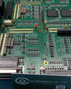 Today’s drivers expect far more than a basic radio. Modern infotainment systems provide navigation, smartphone integration, Bluetooth connectivity, voice recognition, streaming media, backup camera displays, and touchscreen controls.
These sophisticated systems require high-performance PCB assemblies capable of processing large amounts of data while maintaining stable power distribution and dependable operation.
At YIC Assm, we manufacture PCB assemblies that support high-speed communication, signal integrity, and efficient power management, helping automakers deliver seamless in-vehicle experiences.
Supporting Electric and Hybrid Vehicles
As electric vehicle adoption continues to grow worldwide, automotive electronics have become even more critical. Electric vehicles depend on numerous interconnected electronic systems to maximize performance, battery life, and driving range.
PCB assemblies play an essential role in:
- Battery Management Systems (BMS)
- Charging systems
- Power distribution
- Motor controllers
- Inverters
- DC-to-DC converters
- Thermal management systems
High-quality PCB manufacturing helps improve energy efficiency while ensuring safe operation of high-voltage electrical systems.
Enabling Connected and Smart Vehicles
Connected vehicle technology is rapidly changing how drivers interact with their automobiles. Internet of Things (IoT) integration allows vehicles to communicate with mobile devices, cloud platforms, navigation systems, and even other vehicles.
PCB assemblies support technologies including:
- GPS navigation
- Wireless communication
- Vehicle diagnostics
- Remote software updates
- Telematics
- Fleet management
- Vehicle-to-Vehicle (V2V) communication
- Vehicle-to-Infrastructure (V2I) communication
As connected vehicles become more advanced, reliable PCB assembly becomes increasingly important for maintaining dependable communication and system performance.
Why Manufacturers Choose YIC Assm
Automotive manufacturers require PCB assembly partners capable of consistently producing reliable products while meeting demanding quality standards and production schedules.
YIC Assm provides customized PCB assembly solutions tailored to each customer’s unique application. Whether supporting prototype development or full production, our experienced engineering and manufacturing teams work closely with customers throughout every stage of the project.
Our capabilities include:
- Surface Mount Technology (SMT) assembly
- Through-hole PCB assembly
- Mixed technology assembly
- Prototype PCB assembly
- Turnkey PCB assembly
- Component sourcing
- Functional testing
- Quality inspection
- Medium-volume production
By combining advanced manufacturing equipment with experienced technicians and rigorous quality control procedures, we consistently deliver PCB assemblies that meet the performance expectations of today’s automotive industry.
Quality You Can Trust
Automotive electronics demand exceptional reliability. Every PCB assembly must perform consistently under harsh environmental conditions for many years of continuous operation.
At YIC Assm, quality is built into every phase of production. Our manufacturing processes utilize advanced inspection systems, precision assembly equipment, and comprehensive quality assurance procedures to ensure every completed assembly meets strict industry standards.
Our commitment to quality helps customers reduce defects, improve reliability, and shorten time to market.
Partner with an Experienced Automotive PCB Assembly Provider
As vehicle technology continues evolving toward greater automation, electrification, and connectivity, dependable PCB assembly becomes increasingly essential. Choosing an experienced manufacturing partner helps ensure every electronic system performs reliably throughout the life of the vehicle.
YIC Assm delivers customized automotive PCB assembly solutions backed by advanced manufacturing capabilities, responsive customer service, and a commitment to quality. Whether your project involves advanced safety systems, electric vehicle electronics, infotainment technology, or connected vehicle platforms, our team is ready to help bring your designs into production.
Frequently Asked Question
What industries does YIC Assm provide PCB assembly services for?
YIC Assm serves a wide range of industries beyond automotive manufacturing, including medical devices, industrial controls, telecommunications, aerospace, consumer electronics, and commercial equipment. Learn more about our complete PCB assembly capabilities by visiting our PCB Assembly Services page and discover how our experienced team can support your next electronics manufacturing project.
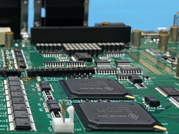
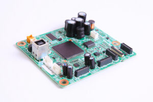 Power supplies, transformers, connectors, and large capacitors are common examples of components that benefit from through-hole mounting. Their secure attachment improves long-term reliability, particularly in environments where equipment experiences repeated movement or harsh operating conditions.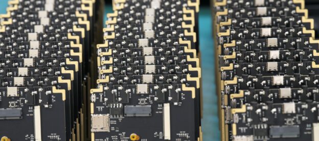
 What Is Turnkey Printed Circuit Board Assembly?
 The ACME PCB Assembly Advantage
 Companies developing electronics—from IoT devices to medical equipment—often depend on rapid prototyping to accelerate development cycles. Working with an experienced partner like
  Modern electronics manufacturing services (EMS) providers combine several technologies to assemble prototype circuit boards:


