Author Archives: Erin

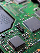
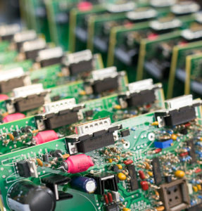
Processor with ball BGA pins

BGA Board Assembly, Rework and Modifications

BGA rework, replacement. Board Assembly uses the most powerful tools to maintain the state-of-the-art production. 

Performance may suffer in mass produced Ball Grid Array (BGA) devices due to many different reasons.  Defects in the device, lack of or excess solder joints, or oversights during upgradation processes can be included as one of the may reasons for performance issues.  These irregularities can be resolved with BGA rework. We provide a comprehensive BGA rework and re-balling services to maintain the efficacy of SMT circuit boards.

8,000 W medium wavelength IR heater measuring 500 mm x 625 mm. The IR/PL 650 XL is Ersa‘s flagship machine for extra large printed circuit boards (PCBs). PCBs up to 20″ x 24″ or 500 mm x 625 mm can now be safely and rapidly reworked. 

Soldering of BGA devices requires precise control and is usually done by automated processes. BGA devices are not suitable for socket mounting.

Board Assembly began offering Ball Grid Array (BGA) Assembly services in the early 90s. Over these many year’s experience BGA assembly with X Ray inspection machine, right assembly procedure, we are very confident to say that we know, and we can build a high quality, good yield rate BGA assembly board.

Ball grid array packaging is a method for reducing package size and integrating a greater number of functions on a single chip module. BGA (Ball Grid Array) also replaces solder balls on the component underside for SMT mounting. Our assembly capabilities include BGA assembly and rework up to 65mm squared up to 36 layer printed circuit board.

BGA (Ball Grid Array) board assembly, rework, and modifications are common processes in electronics manufacturing and repair. Here’s an overview of each process:

  1. BGA Board Assembly:
    • BGA assembly involves mounting BGA components onto a PCB (Printed Circuit Board). BGAs have solder balls beneath the component that are used to make connections to the PCB.
    • The assembly process typically involves solder paste deposition onto the PCB pads, placement of the BGA component onto the pads, and reflow soldering to melt the solder and create electrical connections.
    • Proper alignment, solder paste application, and reflow profiles are critical for successful BGA assembly.
  2. BGA Rework:
    • BGA rework is necessary when there are defects in the initial BGA assembly, such as insufficient solder, solder bridges, or misalignment.
    • Rework can involve the removal of the faulty BGA component using specialized equipment like a rework station or reflow oven. This process often requires careful heating to avoid damaging the PCB or surrounding components.
    • After removal, the site is cleaned, and fresh solder paste may be applied if necessary. Then, a new BGA component is placed and reflow soldered.
  3. BGA Modifications:
    • BGA modifications are changes made to the BGA components or PCB after the initial assembly process.
    • This can include upgrading components, changing the BGA footprint, or adding/removing features on the PCB.
    • Modifications may involve removing existing components, adding new ones, cutting traces, or making changes to the PCB layout.
    • Care must be taken to ensure that modifications do not adversely affect the functionality or reliability of the circuit.

Common tools and equipment used in BGA assembly, rework, and modifications include:

  • Reflow ovens: Used for melting solder paste to create electrical connections during initial assembly and rework.
  • Rework stations: Equipped with heating elements and hot air nozzles for precise heating during BGA removal and placement.
  • Soldering irons: Used for touch-up soldering and fine-detail work.
  • Flux: Used to aid in soldering and rework by improving wetting and preventing oxidation.
  • Solder paste dispensers: Used for applying solder paste to PCB pads before BGA placement.
  • Inspection equipment: Including magnifying glasses, microscopes, and X-ray machines for inspecting solder joints and connections.

BGA assembly, rework, and modifications require skill, experience, and attention to detail to ensure the reliability and functionality of electronic devices.

Contact Us for more information.

thru hole YUN INDUSTRIAL

Why Consider Using Through Hole Printed Circuit Boards?

Why Consider Using Through Hole Printed Circuit Boards?

In the printed circuit board business, there are two primary ways to mount components onto the circuit board: through-hole mounting and surface mounting. Through-hole mounting is the older technology and requires the circuit board manufacturer to drill holes through the PCB and place leads into the holes. More recently, surface mounted technology has taken over the field.

Through-Hole Components

Through-hole components come in one of two types of leads, radial and axial. Axial through-hole components run along the axis of symmetry of the component while radial components protrude in parallel from the same surface on a board.

Components of Surface Mount Technology

When you look at any modern PCB design, you will see SMT technology in most instances. Surface mount technology (SMT) is the most commonly used technology today. These types of boards and components have very small or no leads at all as their primary purpose is to be soldered directly on the surface of a PCB during the design process. This method allows for components to be much smaller, allowing for greater density and better overall performance on a smaller circuit board.

With surface mounting offering so many benefits, why even consider through hole flex printed circuit boards?

The reason is that through hole mounting offers stronger mechanical bonds. This makes through hole flex printed circuit boards the better option for devices that are designed to undergo major stresses, like sudden accelerations, collisions, or extreme temperatures. This makes them worth considering for military, automotive, and extreme sports applications.

Yun Industrial Acme PCB Assembly is capable of two types of printed circuit board assembly services. They are full and partial turn-key services. Full turn-key covers all aspects of PCB fabrication and assembly, including manufacture of PCBs, parts procurement, quality inspections, and final PCB assembly.

Printed circuit board production

Surface Mount Technology (SMT) vs. Through-Hole Technology: Pros and Cons

In the ever-evolving world of electronics manufacturing, choosing the right assembly method is crucial for optimizing both performance and cost-efficiency. Two prominent techniques in this realm are Surface Mount Technology (SMT) and Through-Hole Technology. Each has its own advantages and drawbacks, making it essential to understand their unique characteristics and applications.

Printed circuit board productionSurface Mount Technology (SMT) has become the industry standard due to its efficiency and versatility. SMT involves mounting electronic components directly onto the surface of printed circuit boards (PCBs). This method significantly enhances the automation potential, allowing for high-speed production and reduced labor costs. The compact nature of SMT components enables the design of smaller and lighter devices, a crucial factor in modern electronics where space and weight are at a premium.

One of the key benefits of SMT is its superior performance in high-frequency applications. The reduced lead length in SMT components minimizes the parasitic inductance and capacitance, leading to better signal integrity and faster operational speeds. This makes SMT the preferred choice for complex and high-speed circuits commonly found in telecommunications, computing, and consumer electronics.

However, SMT is not without its challenges. The smaller component size can make manual handling and inspection difficult, necessitating advanced automated inspection systems. Additionally, SMT components are generally less robust in terms of mechanical strength compared to their through-hole counterparts, which can be a consideration in applications subject to high mechanical stress.

On the other hand, Through-Hole Technology has been a staple in the industry for decades. This method involves inserting component leads through pre-drilled holes in the PCB and soldering them on the opposite side. The primary advantage of through-hole technology is its mechanical stability. The strong solder joints created by this method are highly reliable, making it ideal for applications where durability and longevity are paramount.

Through-hole technology also excels in high-power and high-voltage applications. The robust nature of the components allows them to handle greater electrical currents, making through-hole technology indispensable in industries such as automotive, aerospace, and industrial equipment. Additionally, through-hole components are easier to handle and inspect manually, which can be beneficial for prototyping and low-volume production.

Despite its strengths, through-hole technology has its limitations. The manual insertion process is labor-intensive and time-consuming, leading to higher production costs and longer assembly times. The requirement for drilled holes also reduces the available space on the PCB for routing signals, potentially limiting design flexibility and increasing the board size.

In conclusion, the choice between SMT and through-hole technology depends on the specific requirements of your project. For high-speed, high-density, and cost-sensitive applications, SMT offers unparalleled advantages. Conversely, for high-reliability, high-power, and mechanically robust applications, through-hole technology remains a superior choice. Understanding the pros and cons of each method allows manufacturers to make informed decisions that align with their production goals and application needs.

For more detailed information on our SMT assembly services, visit our Surface Mount Technology Assembly page. Explore how we can help you leverage the strengths of SMT to achieve your project objectives.

What Does It Mean to Be a Full-Service PCB Assembly Provider?

If you are in need of fully assembled printed circuit boards (PCBs) for your products, but you don’t know where to start, this article will guide you in the right direction. If  you don’t have any printed circuit boards or any of the parts, and you certainly don’t want to burden your limited staff with the task of putting all those PCBs together, you will need a full-service PCB assembly provider.

Printed Circuit Board FabricationACME PCB Assembly is an ISO 9001:2015 certified EMS. We make sure you get best price with highest quality, on time delivery schedule. All PCBs are meet the high standards established by the IPC 600. Since ACME PCB Assembly is a IPC certified trainer for IPC A-610, we know how important the quality of bare board is, and we know what can drive the PCB Assembly labor higher.

Being a full-service PCB assembly provider means that we handle every aspect of the project. You just give us your specs, and we’ll do everything else, including:

At Acme PCB Assembly, we have the experience, the vendor relationships, and the well-trained staff of fulfill your PCB order. The great thing about full-service PCB assembly is that you don’t have to worry about a thing. You don’t have to find the right parts vendors or ship materials to us. We handle everything.

We closely match new incoming inquiries to board house equipment and capabilities, ensuring you receive only those inquiries that you are interested in Acme Circuit board assembly provide PCB fabrication service in the development and manufacturing of quality single, double sided and Multi-Layers printed circuit boards for the computer, medical, transportation, communication, aircraft, aerospace and related industries.

Of course, if you already have printed circuit boards on hand and the PCB components you need, then you can also opt for partial service.

Contact us today to learn about all of our service options, including our add-on services.


Stacked circuit boards

How you Would Create an Electronic Prototype

How to Create an Electronic Prototype

Do you have a big idea for a new electronic product? We all know that ideas are a dime a dozen, so if you really want to get your idea off the ground, eventually you’ll need to create a prototype. A prototype, simply put, is a physical manifestation of a product. There are many important reasons to create a prototype. In this article, we’ll also review some quick tips about how to turn your idea into a prototype.

Why Prototype?

Creating a prototype is an essential step in your journey to bring your product to market. One of the biggest reasons to create a prototype is to simply work out all the bugs and kinks. Designing the prototype will help you determine if you’ve got the size right, if it can really work as you’ve imagined, and what the best materials are.

A prototype is also practically a requirement if you’re looking for seed money. No investor is going to write you a check if you aren’t at least serious enough to show them an early model of your product.

How to Create a Prototype

prototype-assembly-YUN-INDUSTRIAL-1

A prototype starts with a drawing. You can take an actual pen to paper for this step, but eventually it’s a good idea to either create or commission a CAD drawing (computer-aided design), which will provide greater detail and accuracy.

Next, you may want to try and build a preliminary prototype of y our product just to test out the dimensions and see what it will look like. This will not be a working prototype. If you are handy, you may be able to fashion it yourself using foam, moldable plastic, metal, wood, or parts from other products.

Eventually, though, you’ll want to create a working prototype. This will be important to showcase to investors. Since you are creating an electronic product, it is likely that you’ll want to work with professional prototype developers. These are manufacturers who specialize in developing prototypes. They are experienced in helping entrepreneurs and inventors just like you figure out how to actually create the prototype. For example, they can help you determine the right materials and figure out how the actual product will work.

At Yun Industrial Acme PCB Assembly, we can help you create your electronic prototype. Send us your CAD drawing and other paperwork, and let’s get started on building your product!