In the world of medical device manufacturing, few components are as essential as Printed Circuit Boards (PCBs). These small but powerful platforms are the backbone of modern medical technology, ensuring that devices perform accurately, safely, and reliably—especially in life-saving situations.
Today’s medical devices, from pacemakers and defibrillators to wearable monitors and diagnostic equipment, rely on compact, high-performance PCB fabrication to function at their best. But what exactly makes PCBs so critical to this industry?
 Compactness and Efficiency in Medical Technology
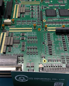
As medical technology evolves, devices are becoming smaller, smarter, and more portable. This push for miniaturization demands printed circuit boards that are both compact and capable of handling complex operations in tight spaces. Whether it’s a handheld diagnostic tool or an implantable medical device, PCBs allow engineers to integrate multiple functions within a single, space-saving platform.
Custom PCB Fabrication for Specialized Medical Applications
Every medical device has unique requirements. That’s why custom PCB fabrication is essential in this industry. Each board must be carefully designed to meet strict technical and regulatory standards.
From high-resolution imaging systems like MRI machines to portable glucose monitors, custom-designed PCBs ensure accuracy and functionality across diverse medical environments. Tailored layouts, trace designs, and component placement all play a role in the precision performance of the final device.
Uncompromising Reliability and Quality Standards
When patient health is on the line, there’s no room for error. PCBs used in medical devices must meet the highest standards of reliability and consistency. Any malfunction or failure could lead to serious consequences.
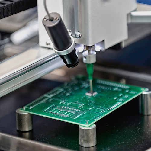
As a result, the PCB fabrication process for medical devices follows rigorous quality control procedures. Every board undergoes careful inspection and testing to ensure it performs flawlessly, even in demanding conditions such as sterilization, extreme temperatures, or high electromagnetic interference.
Safe Materials and Sterilization Compatibility
Medical PCBs must also comply with safety and sanitation requirements. Materials are selected based not only on performance but also on biocompatibility and sterilization resistance. For example, boards used in surgical tools or implantable devices often need to withstand autoclaving, UV exposure, or chemical cleaning agents.
This adds complexity to the PCB fabrication process and highlights the importance of working with a trusted partner that understands the specific needs of the medical industry.
 Supporting the Shift to Digital Healthcare
Modern healthcare relies heavily on real-time data—whether it’s monitoring patient vitals, powering sensors, or supporting communication between devices. High-speed printed circuit boards enable fast, accurate data transmission, ensuring that medical staff and patients receive reliable performance from their devices.
As medical devices grow smarter and more connected, the role of PCBs in supporting digital innovation continues to expand.
Driving Innovation in Medical Device Manufacturing
The demand for next-generation medical technology is pushing PCB design and fabrication into exciting new territory. With advancements in flexible PCBs, high-density interconnects (HDI), and miniaturized components, today’s boards are helping bring cutting-edge solutions to life.
At the heart of this progress is reliable, high-quality PCB fabrication—the foundation for medical devices that deliver life-saving care with precision and confidence.
Partner with a PCB Fabrication Expert You Can Trust
At Board Assembly, we understand the critical role Printed Circuit Boards play in medical devices. Our U.S.-based team is experienced in fabricating and assembling PCBs that meet the exacting standards of the healthcare industry.
Whether you’re developing a new device or improving an existing design, we’re here to help you build with reliability, safety, and innovation in mind.
 Back Home
 1. Understand Your Application Requirements
 Choosing the right